Angled Slicing

3d printing in a 45 degree plane made possible by using Cosine Additive’s Solidworks slicing addin/plugin

Traditional 3D printing uses a slice plane parallel to the XY plane and translates that plane vertically through the part to create slice layers for printing. While this is incredibly common, it creates some limits for traditional FFF 3D printing. Overhangs require support to print, parts may need to be broken up into multiple prints, and the weakest direction of the print will always be the Z axis. The ability to angle the slice plane reduces these restrictions and broadens the range of geometries that can be 3D printed.

Implementing Angled Slicing

Before getting into the details of how to perform angled slicing, I’m going to present below an incredibly useful conceptual idea that will simplify this slicing technique. Instead of angling the slice plane, rotate the part until the desired slice plane is parallel with the XY plane, then perform the slicing as usual. Finally, after all the layers have been sliced, apply the inverse rotation to return the layers back to their original orientation.

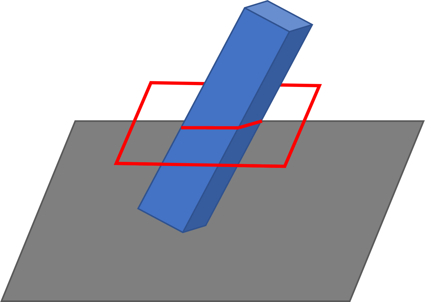
This rotation into the XY plane simplifies the mathematics used for slicing as now everything necessary for slicing can be defined with two dimensions instead of three dimensions.

The first step to angled slicing is to define the slice plane. The Cosine Slicer does this by representing the plane as a set of three angles. Each one is the angle between the slice plane and the XY plane along either the X, Y, or Z axis. With these angles, quaternions are used to rotate each triangle in the part to its new orientation. Now with the slice plane being parallel to the XY plane, the slicer can move the slice plane through the part along the Z axis, creating the slice layers. Once the layers are created, the slicing engine uses the slice plane angles to rotate each slice layer back into its original orientation. The end results are layers that are sliced in three dimensions.

Applications

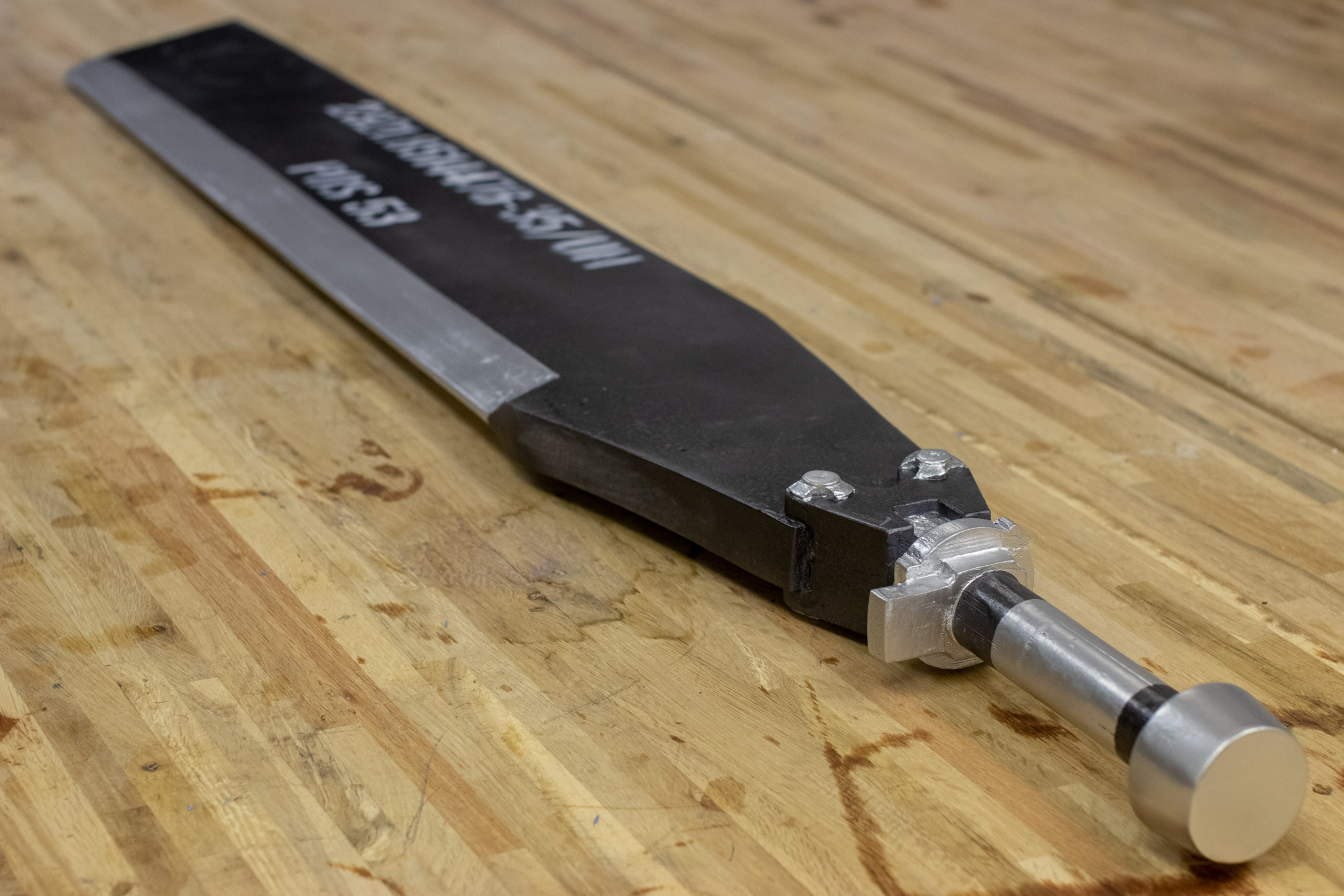
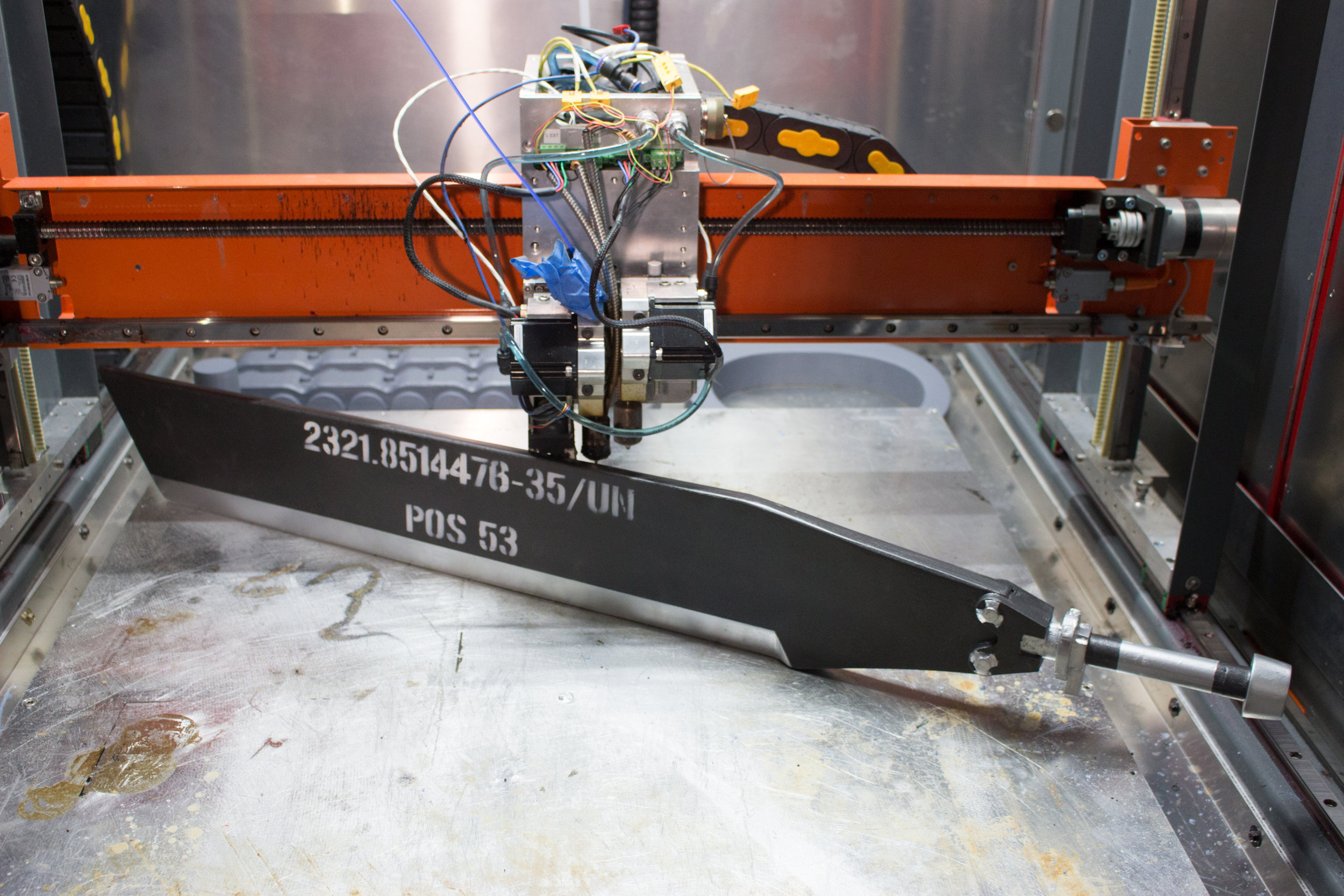
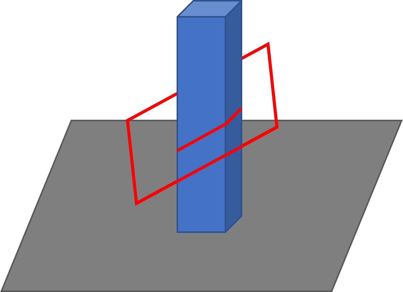
In this section are a couple of examples that show how angled slice planes can significantly reduce print time, complexity, and material usage. The first example is printing the square tubing shown below.


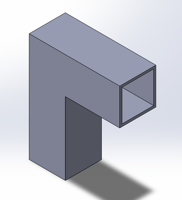
With traditional printing, this part would require support under the unsupported, right-angle portion of the tubing and within that section of tubing to support the top of the tube. The support would increase the print time of the part significantly, increase the material required to print the part, and increase the surface roughness along the area where the support interfaces with the part. There is also the labor that goes into removing the support and the risk of damage to the part during the support removal.

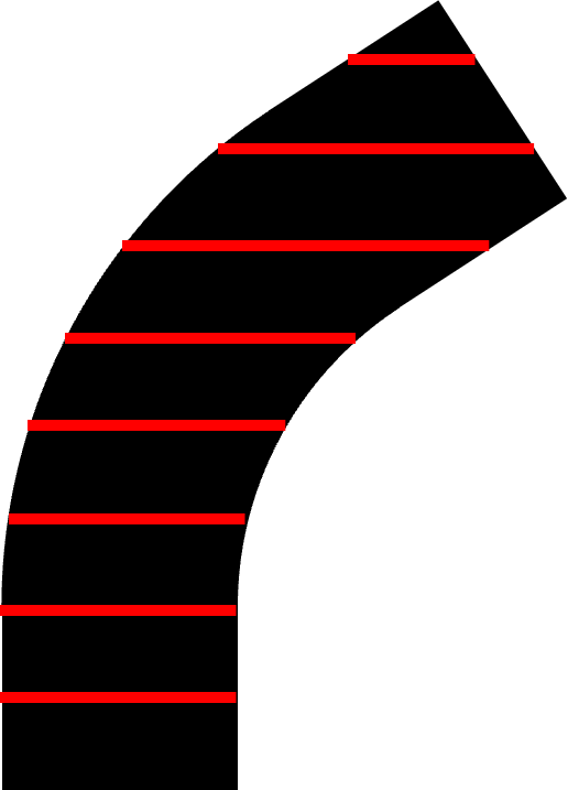
With angled slicing, the vertical portion of the tube can be printed as normal, and the horizontal portion can be printed using an angled slice plane. The horizontal portion of the tubing can be printed on the sloped surface of the vertical tubing as the base for this section of the print. This would eliminate the need for support both under the horizontal section of tubing and within that same section of tubing. The resulting slice planes are shown in the image to the left.

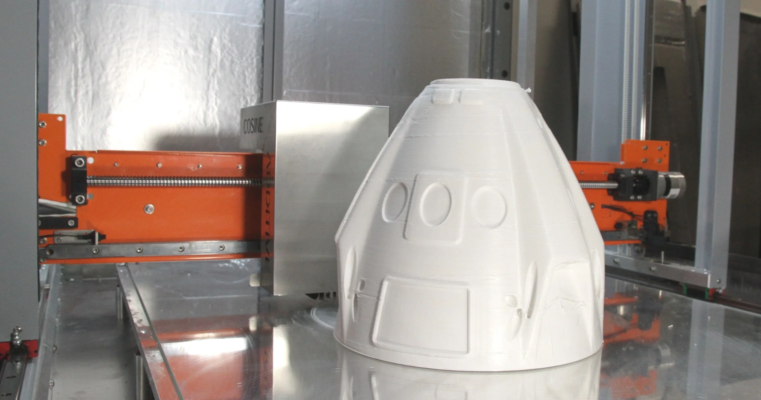
This same technique can be used to print hollow object without the need for any internal supporting material, such as boxes or spheres. Normally, to print a hollow box, the part would have to be split into two halves and combined after the fact. The alternative would be to create a raft and support structure under the box and print it while balanced on its edge. This eliminates the need for internal support material and leave the inside of the box hollow. This would allow the print to be done as one piece, but increases the complexity and material usage, and would require labor to remove the support material. Just like the horizontal section of tubing above, an angled slice plane would allow the box to be printed in one piece while sitting flat on the bed and require no support material.

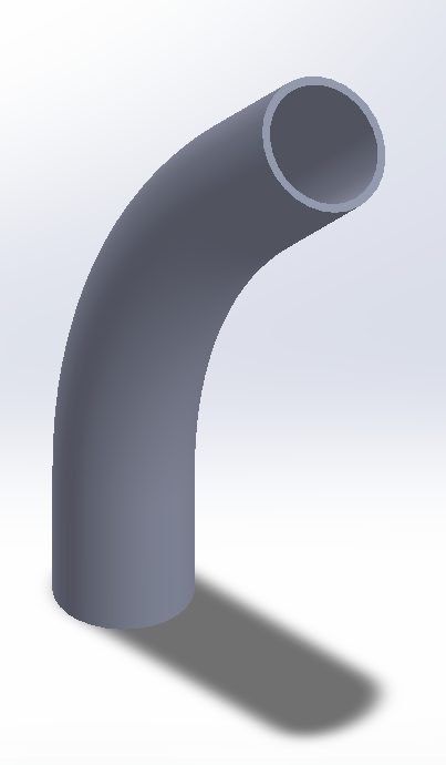
Finally, an incredibly powerful application of angled slice planes is seen when printing angled ducting or piping. The Cosine Slicer can dynamically adjust the angled slice plane through a bent section of pipe so that the slice plane is perpendicular to the normal of the pipe cross-section. This will maximize the hoop strength of the pipe and minimize the use of support material. Dynamically angled slice planes can even be combined with vase mode printing to create continuously extruded custom contoured piping or ducting.


Conclusion

Angled slicing is a powerful tool in the 3D printing toolbox. Not only does it increase the scope of 3D printing applications, but it also provides a smarter alternative for some existing applications.

2k Thermoset Technology At Cosine Additive

2k Thermoset Technology At Cosine Additive

Thermoset extrusion technology has revolutionized the way that many industries manufacture and process materials. From automotive parts to construction materials, thermoset extrusion has become a key method for producing high-quality, durable products with precise dimensions and consistent properties. In this blog post, we will explore the basics of thermoset extrusion technology, including how it works, its benefits and drawbacks, and its applications in various industries. We will also discuss the future of thermoset extrusion and how it is expected to shape the manufacturing landscape in the coming years. Whether you are a seasoned professional or new to the field, this blog post will provide you with a comprehensive overview of thermoset extrusion technology and its place in modern manufacturing.

Cosine Tools For All Your Printing Needs

Cosine Tools For All Your Printing Needs

The line up of 3D printing extruders boasts impressive capabilities, offering a range of materials and a high level of precision. These extruders are designed to be plug-and-play, making it easy for users to get started with minimal setup. In addition to their ease of use, these extruders also offer full software control, allowing users to customize and fine-tune their printing processes to achieve the best possible results. Whether you're a seasoned 3D printing professional or a beginner, these extruders provide the versatility and control you need to bring your creations to life.

Automated Pellet Feed Delivery System

The automated pellet material feeding system in this industrial 3D printer makes it easy to continuously print large parts without the need for manual intervention. The closed-loop vacuum system ensures that the pellet material is fed smoothly and consistently into the extruder, resulting in improved print quality and reduced waste. The system is fully automated, allowing users to focus on other tasks while the printer is running. This advanced technology helps to increase productivity and efficiency in the 3D printing process, making it a valuable addition to any industrial setting.

Milling in your 3D printer

Milling is the process of machining using rotary cutters to remove material by advancing a cutter into a workpiece

Milling in your 3D printer provides multiple advantages such as speed, accuracy, and versatility. 

Cosine Additive uses milling to achieve tight tolerances and also allows us to quickly print the net shape then quickly surface the part to produce parts in a timely manner. 

Induction Heater 

Induction heating is the process of heating electrically conductive materials, namely metals or semi-conductors, by electromagnetic induction through heat transfer passing through an induction coil that creates an electromagnetic field.  

Induction heating in 3D printing rapidly decreases the amount of time it takes to heat up the nozzle. 

Cosine Additive is using this to accurately control the heat up and cool down of the nozzle while 3D printing. This will reduce ooze between rapid motions, finely control material and part temperature, prevent over temping, and many more applications. 


Vacuum Bed Printing Surface

Vacuum Bed Printing Surface

The 3D printing bed on this machine utilizes vacuum pressure to securely hold the build sheet in place during the printing process. This ensures that the print remains stable and produces accurate results. The bed's subassembly is able to reach maximum temperatures of 100 degrees Celsius, making it capable of handling a wide range of materials. This versatility allows for a greater range of printing possibilities, including the use of high temperature materials such as polycarbonate. The vacuum pressure and high temperature capabilities of this 3D printing bed make it a reliable and efficient choice for any 3D printing project.

AM1 Chain Drive vs Belt Drive

A lot of traditional 3D printers utilize a series of belts and motors to produce motion. Consumer grade FFF (Fused Filament Fabrication) printers use belt-driven movement for the X and Y, along with a ball-screw system for the Z axis. We began looking internally for alternatives for our own belt-drive system, and under the same operating conditions, chains were found to be cheaper, easier to order with shorter lead-times, and a lot more compatible hardware that can be found off the shelf. On the AM1 line of machines, the Y bridge is an aluminum billet construction with robust, industrial grade extruder tools. This can add substantial load to the Z axis, which shortens the lifespan of the belt. Also, when compared to chain systems, belt systems require more hardware to install and maintain. 

Cosine Y-Bridge Complete Assembly

Since switching to a chain drive for the Z, we have seen an increase in the lifespan of the system, with significantly less deflection under load. This improves the accuracy of the Z axis during printing and produces more consistent layers throughout prints.  Belts also require periodic maintenance to re-tension the system as the belts plastically deform over time, an issue not seen with belt driven systems.

Although it does not happen often, some belt systems have been known to snap due to an excess of force acting on the Z system, especially when the belts are older and not maintained as well. This cripples the system and translates to a list repairs and maintenance. From in-house testing, the chain system can withstand a much larger amount of stress and force than any belt system of similar size; making it so that the chain system is not a likely point of failure.


Enhanced Debugging Tools

Here at Cosine, we have a diverse array of customers from different industries. More often than not, we have found that our customers do not want their printer to be connected to the internet because of security or intellectual property (IP) concerns. This presents a problem for us when it comes time to troubleshoot issues because remoting into the printer and diagnosing the problem is not possible. We instead have to tell the customers what files to email to us.

To help account for this issue, we created what we call Enhanced Debugging Tools. These tools are used in a couple of different spots in our software. The first being the Export Error Logs button. All this button does is create a zip file of the two error logs (one for the Dashboard and one for the CosineAdditiveService). This is a very simple but valuable tool because half the time when an issue occurs, it is caught and logged in one of those error logs. Another tool is the ability to export information surrounding a specific print. When print issues occur, we have customers send over the post processed print file to help us determine the cause of the problem. To simplify this process, we created a checkbox in the Print History tab and a corresponding button in that tab, so the customer can select which prints they are having trouble with and then hit the button to export the information. There are a couple of different things that get exported during this process. The first is the post-processed print file, as mentioned before. Second is the truncated error logs that only contain errors that occurred during the time that the print was running. Finally, information about the selected material and a log of all database communication during the time the print was running. As mentioned before, some customers have IP or security concerns, which means that sometimes they cannot send us the actual print they are having trouble with. We have accounted for this as well by having a popup when they go to export the prints that asks if they want to include geometry or not. If they don’t want to include geometry (which is essentially the main part of the print) then the outputted file would just contain the header comments which shows us things like what slicer and machine settings they are using.

The combination of these tools helps immensely in cutting down the time it takes to troubleshoot an issue. Previously, the manual process for collecting information from offline printers was tedious and prone to error. These new tools help automate that process and decrease our turnaround time when resolving issues. Here at Cosine, we strive to provide a quality service for a quality product, and this is just one more step towards that goal.

Advanced Work Coordinate Systems

We wanted to highlight some of our new features in the blog, one of which is the Advanced/Extended Work Coordinates System.

If you have a background in the CNC world, then you will be well acquainted with Work Coordinate Systems, and if you are familiar with Cosine’s machines, then you know that we have been utilizing Work Coordinate Systems already. For the uninitiated, I will provide a brief overview.

A Work Coordinate System is essentially a reference point for the origin of a machine. If we change the Work Coordinate System, we change where the origin is. Changing the origin allows us to move where on the bed a part is printed. This is helpful in many situations, one of which is that you just finished a print on one section of the bed, and you want to print the same thing but on a different section of the bed. Instead of reslicing the print so that it is moved to the different part on the bed, you would just change your Work Coordinate System and then proceed with your print.

So that is a brief overview of what a Work Coordinate System (or WCS) is. Now we will discuss what we call Advanced Work Coordinate Systems.

When we previously used WCSs, we would have only a single WCS that would be overwritten upon each change. Now we can choose from up to 9 different WCSs, that we can modify individually to fit our needs. The 0 index WCS is what is known as the Machine Coordinate System because it cannot be edited by the user, and it always has offsets of 0. Also, as mentioned previously, we were able to only change the offsets for the X, Y, and Z. With the new Advanced Work Coordinate Systems, we can now also change the offsets for the A, B, and C axes (only relevant for machines that have those extra axes), as well as the Yaw, Pitch, and Roll.

The offsets for the Pitch, Yaw, and Roll offsets enable us to do more things that we previously were not able to. When these offsets are changed (their units are degrees), you can rotate around the X, Y, and Z axes by the degree offset that you set. This allows us to do things such as align the coordinate system to an object that you are printing on or to account for some error in the print surface we are printing on, such as if the print surface is misaligned in the y axis all without having to modify the g-code we are printing.

Advanced Work Coordinate Systems open up many more printing possibilities and we are excited to see how our customers end up using this feature!

US Marines Mobilize 3D Printing with Cosine

Cosine Additive supports the Armed Forces and when the Marines contacted us, we were ready for duty. The US Marine Corps are currently pursuing a project called X-FAB and the AM1 Industrial 3D Printer of Cosine is the core of their project.

A year ago, the Marines came to Cosine with one mission, knowing that we’re the solution.

XFAB_Photo4_wLogo.jpg

During their latest deployment in Afghanistan, they had a problem with one combat vehicle. The mount of the screen that helps the gunner to aim the main gun broke during operations, and no amount of duct tape was able to solve the problem. Without that screen, the weapon systems of the vehicle were inoperable, severely reducing the combat efficiency of that unit in case they encounter a Taliban ambush.

ECP1.jpg

They ordered a new frame, but it took one week for the logistics command to process the order, another week of the company in the US to make the frame, another one to ship the frame to Afghanistan, and once in Afghanistan it took them TWO WEEKS to receive the frame on the Forward Operations Base (FOB).

By that time, the Marines had finished their deployment and were stationed in Japan.

We helped our fellow Marines by sending them their own AM1 XL 3D printer to be used in their mobile manufacturing unit. Finally, the Marines can use this large 3D printer to give them the quick repairs that they need in the battlefield… and FAST.

Here is an image of a 3D printed mount like the one in the story, but with one change. What in the past took them 4-5 weeks to acquire, they were able to 3D print in just ONE DAY.

Bracket.jpg

After deploying the AM1 on the latest NATO exercise in Norway, the Marine Corps is very pleased with the results:

'“The AM1 has greatly improved our flexibility in the battlefield, allowing us to have a quick turnaround of parts to keep vehicles and units operational on the roughest environments.”

- Master Srgt McCue

m54mnew2[2].jpg

Software Updates

code.jpg

In order for our industrial 3D printers to work properly, we need to make sure they are in the best shape that they can possibly be. We do this by adding all the necessary minor updates every week and major updates every month.

Recently, we’ve added several software updates that greatly improve the printer’s performance.

EXTRUSION MULTIPLIERS - We can have different extrusion multipliers for the outer perimeter, the inner perimeter, the infill, the solid infill, and the support. This is a level of control we are currently unable to achieve by using a slicer alone. This gives our printers a significant improvement in print speed and quality.

ExtrusionMultiplier.PNG

PRINT RECOVERY - we added a print recovery feature. This will allow us to recover a print if it fails in the middle of the process so we don’t lose the print. By not having to restart a failed print, you save a lot of time, effort, as well as material.

PrintRecovery.PNG

DEVIATION - we now have the ability to change the deviation for different sections of a print. For example, we can increase the deviation for just the infill, which will round the corners. By rounding the corners of just the infill section, we are able to dramatically increase the print speed of the overall print, without sacrificing the quality of the print.

Deviation.PNG

Contact us to receive our monthly newsletters and stay up to date with our software updates and custom 3D printing parts!

Edge of Tomorrow Sword

Ever fantasized about wielding your favorite weapon from your favorite movie or TV series? Fortunately enough, we were able to experience that feeling with the helicopter sword from the blockbuster movie, Edge of Tomorrow!

Our first step was to obtain an STL file to import into the AM1. We contacted DmitriyKotlyar, an extremely talented artist that designed the Heli Blade. We will leave you the link to his CG Trader here: https://www.cgtrader.com/3d-models/military/melee/heli-blade-from-edge-of-tomorrow

heli-blade-from-edge-of-tomorrow-3d-model-obj-mtl-stl-sldprt-sldasm-slddrw-ige-igs-iges-stp-bip.jpg

After adding the file into the AM1 Industrial 3D printer, we slice the sword in TWO so we can have the best detail in both faces.

By doing that, we also save precious time and materials in case something went wrong.

80C801A7-EFB1-4D6C-A7D8-38661D2A8F68.jpg

The material that we chose was PC+PBT (polycarbonate + polybutylene terephthalate). This material is as stiff as it is ductile, highly chemical-resistant, with good structural integrity, excellent load-bearing performance, and drop impact resistance (in case our client ... or us… had some watermelon slicing to do). This material is easy to print, but requires a heated build chamber to print in large scale.

IMG_1477.jpeg

We started the print with a 1.0 mm nozzle and a 0.1 mm layer height. We input as a personal touch a honeybee shape filler to make it as lightweight as possible, but also have a high impact distribution and resistance. Basically, we made it wieldable.

Each side took 12 hours to print. Overall, 2 working days in total.

CC1B8DDF-7E43-4194-8DF6-DFC45107F287.jpg

After those two days, we glued each side with Epoxy. This glue is very efficient and widely used for XL or Big 3D printed parts. When its dry, the Epoxy is so strong it’s almost guaranteed it won’t come undone.

Now that we had a unified sword, we sanded down any imperfections. We started with an 80 grid on the flat side, and finished with a 240 grid for a smoother texture and to preserve the details on the hilt.

After all these steps, we just had to do the painting.

We start with a coat of primer to fill any gaps and to ensure that the black paint is going to be well attached to the sword. Then, we wait until the paint has dried and we paint the silver details.

IMG_1599.jpeg

Finally, we 3D printed a stencil, that we sprayed white paint on top of the sword.

When we finished, we thought it would be a great idea to slice a watermelon with it… and FILM IT! Scroll down to watch the whole video!

To be honest, we were not quite sure if the sword would even cut halfway through the watermelon. But to our complete surprise, it sliced ALL THE WAY!

From start to finish, this project was extremely fun and we are really excited to do it again.

Please let us know when you need our help creating your next prop!

If you are interested in buying your own Edge of Tomorrow Sword, Sanded, Primed & Painted 45"(1.14m) it’s only $720!

Web Analytics