
The term “Operation” is going to appear often when discussing the Cosine Slicer, but what exactly is an operation when it comes to slicing? We use the term to mean a specific algorithm that generates toolpathing in a particular way. For example, infill, shell (part walls), or support would each be different operations. These are considered unique operations, because the algorithm that generates infill toolpathing is different form the algorithm that generates shell toolpathing.
As part of the slicing engine, the slicer will convert the Solidworks Part to an STL file and create slices at intervals of your layer height. These slices contain polygons that represent every location where the slice plane intersected the STL. This information is then passed to the selected operations and used to generate toolpathing.
Operation Types
Here are some of the operations currently offered in the Cosine Slicer:
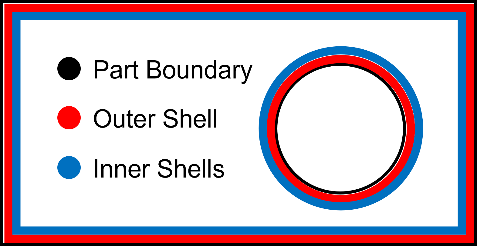
Shell Operation: The shell operation converts the outer walls of the STL into toolpathing offset by half the extrusion width, aka a shell; if the user has chosen more than one shell, then subsequent shells will be offset by the extrusion width. The offsetting is done to account for the volume of the material being extruded. The toolpathing for the outer wall is straight forward, after you offset your polygon path, you traverse the polygon while creating extrusion moves. For the outer walls of the part, subsequent shells are offset inward, and for holes, they are offset outward.
Infill Operation: The infill operation creates a structure inside the part to strengthen it. The amount of infill ranges from 0% for no fill, to 100% for solid parts. There are a couple of different patterns that can be used to create the infill. A rectilinear pattern creates a back-and-forth path that runs from edge to edge across the part. A concentric pattern creates nested paths inside the part that mimic the part geometry. Dam-and-fill is a pattern especially suited for 100% infill with thermoset printing. It creates a shell that encloses the infill area and then extrudes the amount of volume needed to fill in the enclosed space with resin. The resin will flow outward and fill in the entire infill area.


Vase Mode Operation: This operation is tailored towards rapidly producing aesthetically pleasing prints that meet certain conditions. The finished part will only contain a single thickness wall without a solid top or bottom. All holes in the part will be ignored. Also, the part’s outer wall must be contiguous in the slice plane throughout the part. The part will be printed using a single continuous extrusion move that slowing rises in the Z axis while printing. See a more in-depth discussion of Vase Mode printing here.
Manual Operation: The manual operation allows the user to create custom toolpathing code that can be include in the output toolpathing from the slicer. For example, this can be used to set up homing routines at the beginning of the print (if your printer requires homing), preform a wipe routine at the end of each layer, or turn off all the heaters at the end of a print. Any user code created in this operation will be directly output in the final toolpathing.
Sketch Conversion Operation: Due to our integration with Solidworks, we are able to create some unique toolpathing algorithms, such as the sketch conversion operation. This operation can select any 2D or 3D sketch in the Solidworks assembly and convert the sketch into toolpathing code. An application in thermoset print would be to create a sketch along the surface of the part. This “shell” printed over the part would allow the resin to flow into the layer lines of the part and produce a smooth surface.
Other operations currently in production or under development are:
Spiral Operation – creates spiral toolpathing as a fill path for prints.
Positioning Operation – allows the repositioning of axes during a print to aid with subsequent operations.
Probing Operation – defines toolpathing routines for attached probe tools.
Additive Lathe Operation – generates toolpathing to print parts onto a spinning mandrel.
Integrating Operations into the Slicer
A unique feature of the Cosine Slicer is that these operations do not exist within the slicing engine, rather. these algorithms are contained within external libraries that are implementing interfaces through our API and are imported into the slicer at runtime. This means that as long as a library is implementing our interfaces, anyone can create new operations and use them in the slicer. The following are some of the key properties and methods exposed through the API.
OpDefinition: This contains the information the Slicer will need in order to successfully import and run the operation within our framework.
Tools/Materials: The tools and materials associated with this operation.
PartsToSlice: A list of Solidworks parts that this operation applies to.
SlicePlane: A description of the plane that will be used to slice the part. Traditional slicers use an XY plane that moves in the up in the Z axis, but the Cosine Slicer can use any plane defined by the user.
SliceSingleLayer: This method is called while processing each layer of the print and calls the algorithm that creates the toolpathing for that layer.
Conclusion
Hopefully, this post gives you a better understanding of operations and how they are implemented and used within our slicer. Keep an eye out for future posts that will provide in depth explanations for each operations and how the algorithms within them generate toolpathing.