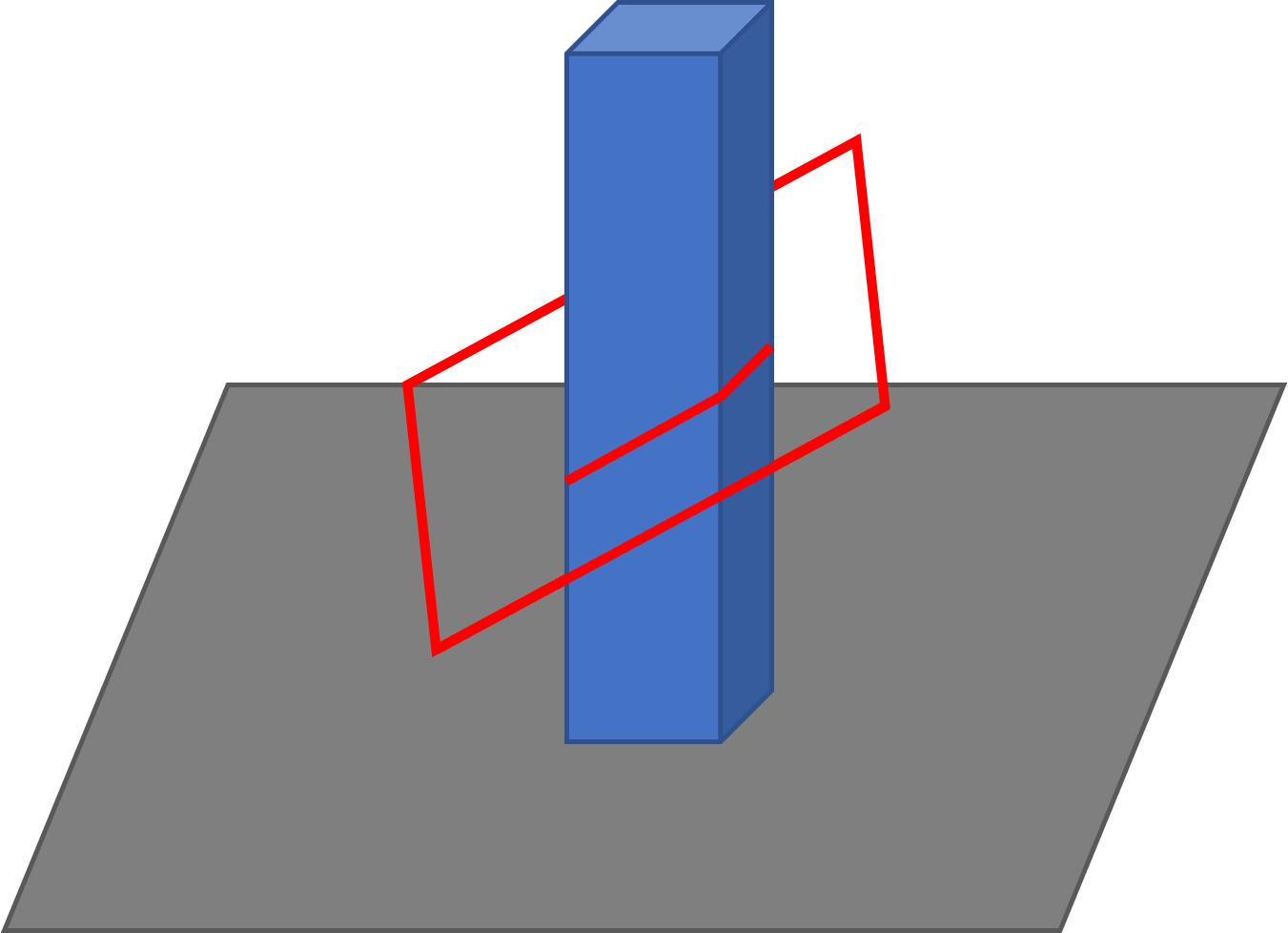
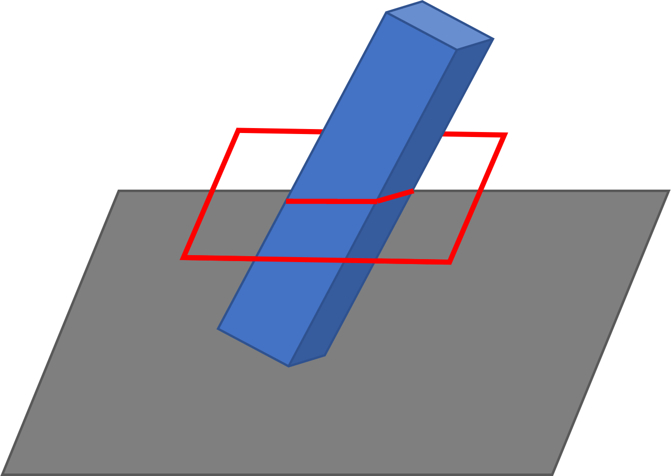
3d printing in a 45 degree plane made possible by using Cosine Additive’s Solidworks slicing addin/plugin
Traditional 3D printing uses a slice plane parallel to the XY plane and translates that plane vertically through the part to create slice layers for printing. While this is incredibly common, it creates some limits for traditional FFF 3D printing. Overhangs require support to print, parts may need to be broken up into multiple prints, and the weakest direction of the print will always be the Z axis. The ability to angle the slice plane reduces these restrictions and broadens the range of geometries that can be 3D printed.
Implementing Angled Slicing
Before getting into the details of how to perform angled slicing, I’m going to present below an incredibly useful conceptual idea that will simplify this slicing technique. Instead of angling the slice plane, rotate the part until the desired slice plane is parallel with the XY plane, then perform the slicing as usual. Finally, after all the layers have been sliced, apply the inverse rotation to return the layers back to their original orientation.
This rotation into the XY plane simplifies the mathematics used for slicing as now everything necessary for slicing can be defined with two dimensions instead of three dimensions.
The first step to angled slicing is to define the slice plane. The Cosine Slicer does this by representing the plane as a set of three angles. Each one is the angle between the slice plane and the XY plane along either the X, Y, or Z axis. With these angles, quaternions are used to rotate each triangle in the part to its new orientation. Now with the slice plane being parallel to the XY plane, the slicer can move the slice plane through the part along the Z axis, creating the slice layers. Once the layers are created, the slicing engine uses the slice plane angles to rotate each slice layer back into its original orientation. The end results are layers that are sliced in three dimensions.
Applications
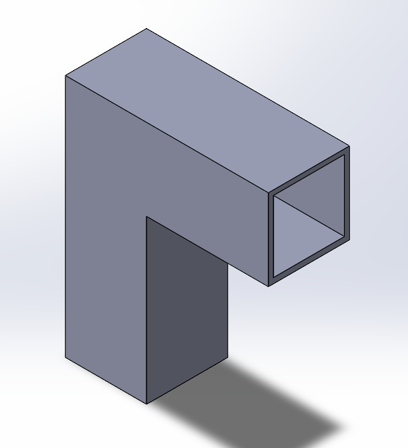
In this section are a couple of examples that show how angled slice planes can significantly reduce print time, complexity, and material usage. The first example is printing the square tubing shown below.
With traditional printing, this part would require support under the unsupported, right-angle portion of the tubing and within that section of tubing to support the top of the tube. The support would increase the print time of the part significantly, increase the material required to print the part, and increase the surface roughness along the area where the support interfaces with the part. There is also the labor that goes into removing the support and the risk of damage to the part during the support removal.
With angled slicing, the vertical portion of the tube can be printed as normal, and the horizontal portion can be printed using an angled slice plane. The horizontal portion of the tubing can be printed on the sloped surface of the vertical tubing as the base for this section of the print. This would eliminate the need for support both under the horizontal section of tubing and within that same section of tubing. The resulting slice planes are shown in the image to the left.
This same technique can be used to print hollow object without the need for any internal supporting material, such as boxes or spheres. Normally, to print a hollow box, the part would have to be split into two halves and combined after the fact. The alternative would be to create a raft and support structure under the box and print it while balanced on its edge. This eliminates the need for internal support material and leave the inside of the box hollow. This would allow the print to be done as one piece, but increases the complexity and material usage, and would require labor to remove the support material. Just like the horizontal section of tubing above, an angled slice plane would allow the box to be printed in one piece while sitting flat on the bed and require no support material.
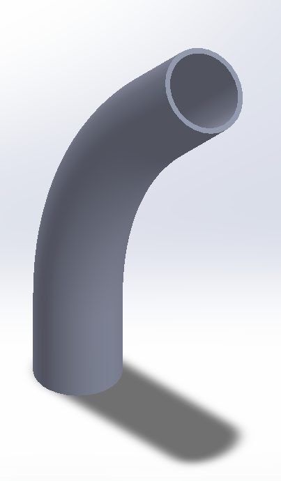
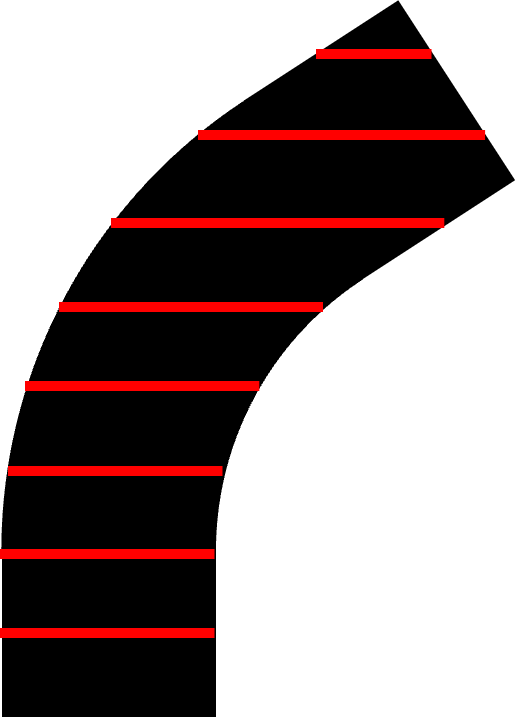
Finally, an incredibly powerful application of angled slice planes is seen when printing angled ducting or piping. The Cosine Slicer can dynamically adjust the angled slice plane through a bent section of pipe so that the slice plane is perpendicular to the normal of the pipe cross-section. This will maximize the hoop strength of the pipe and minimize the use of support material. Dynamically angled slice planes can even be combined with vase mode printing to create continuously extruded custom contoured piping or ducting.
Conclusion
Angled slicing is a powerful tool in the 3D printing toolbox. Not only does it increase the scope of 3D printing applications, but it also provides a smarter alternative for some existing applications.

